
Overview
Procedural generation implies the production of new content based off of certain factors not unilaterally explicitly indicated by any individual. As computers are inherently deterministic systems, it follows that the sole way to produce undefined outcomes is to introduce randomness or noise into generation. This law is ubiquitous, notwithstanding of procedural terrain generation but found in all computer-related fields, notably machine-learning. As such, procedural terrain generation most commonly refers to the derivation of surface-terrain from a series of noise maps which dictate specific features of production.
Although this specific approach is undoubtedly effective for open largely unpredictable terrain, it lacks in reproducibility of certain strictly well-defined patterns which extends from the predictability of certain notable features observed in reality. Such features include trees, rocks, shrubbery, logs, vegetation, or given the specific application desired, roads, buildings, objects, spacecrafts, obelisks all fall under this umbrella.
While it is not impossible to layer noise maps to create specific shapes, and isolate these shapes to stepped noise regions, such an implementation is so unconventional and impractical that apart from extraordinarily unique cases should not even be considered. Another option is to isolate such patterns from procedural generation entirely in both in-game representation and storage, such as replicating a mesh procedurally after each chunk generation, and storing these meshes as individual elements appending the scalar fields used to construct the rest of the chunk. For confined games where further abstraction is unnecessary and unaffordable, this is often the chosen approach. Nonetheless, such an implementation implies a fundamental difference in these patterns in representation and handling even when such dilineation is intrinsicly superficial. In such cases a unified system that does not differentiate such patterns following generation is to be desired.
Background
To understand the necessity of Structure-Planning, it’s beneficial to begin by advancing from a naiive approach. One straightforward approach to Structure Generation is to scatter them by amending chunk information following standard generation. Unlike standard generation, however, this is not achieved on a per-chunk basis, but as a single task revising all chunks.
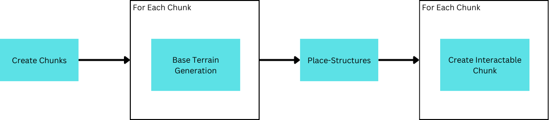
While this functions initially, it introduces a problamatic issue by circumventing the use of chunk-based loading–structures must be fully reloaded everytime new chunks need to be created. By extension this also means all chunks need to be re-created defeating the purpose of chunk loading and slowing down generation considerably. Therefore, structure placement needs to be seperated for each chunk so that only new chunks need to be recreated.
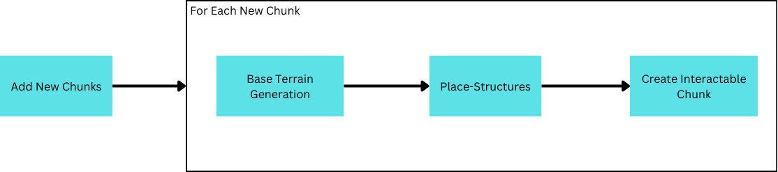
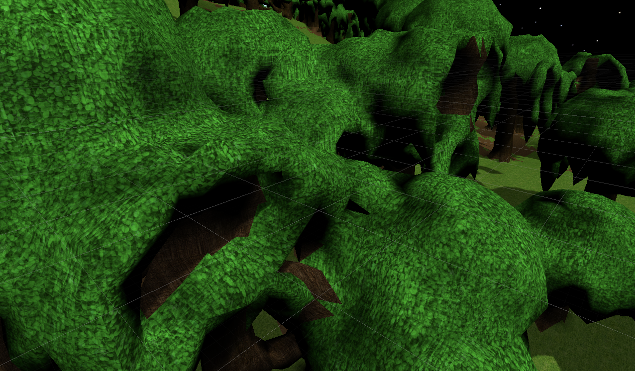
Uh-oh, there’s a problem! Structures placed ontop the border of the chunk are cut-off!
Why is this? Well, as a result of reaffirming chunk-based loading, each chunk is responsible only for generation within its bounds. However, structures overlapping other chunks are malformed as the chunk responsible for placing them is not necessarily the chunk fully responsible for its creation. Instead, the structure needs to inform the neighboring chunk of its existence so it may complete its creation.

Installing this solution, there are several apparent problems. Firstly, extremely large structures may suddenly pop into existence in front of the viewer as they move around. Secondly, moving around enough, memory is gradually consumed until the application ceases to function.
The first problem is caused by the inaccessibility of all the chunk’s pertinent information prior to its first creation. Consider a chunk neighboring a chunk not yet loaded which displays its interactable model. When the neighboring chunk is loaded, it may place a structure that overlaps into the already displayed chunk. Consequently, the pre-loaded chunk is now a modified chunk and must recreate its model. By changing an existing model, part of the structure thus appears by overwriting the existing terrain. This is drastisized by the size of the structure, or more specifically, the distance between where a structure may be placed (inside a newly added chunk), and the extents of its generation (may be inside pre-loaded chunks).
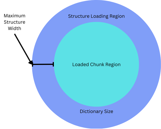
The second problem refers to the difficult nature of releasing structures in this dictionary. Structures overlapping not-yet loaded chunks must be maintained, as if the chunk were to be loaded, it must be aware of the structure. Simultaneously, this suggests that unloaded chunks must also maintain their hash entries as it is possible for new structures to be generated in them. Innevitably, though small, locked hash entires may build up and contribute to increaingly slower gameplay given extended usage.
A popular solution is to maintain a region larger than chunk-loading radius to place structures. In this way, once a chunk leaves this region, its hash entry can be safely released.
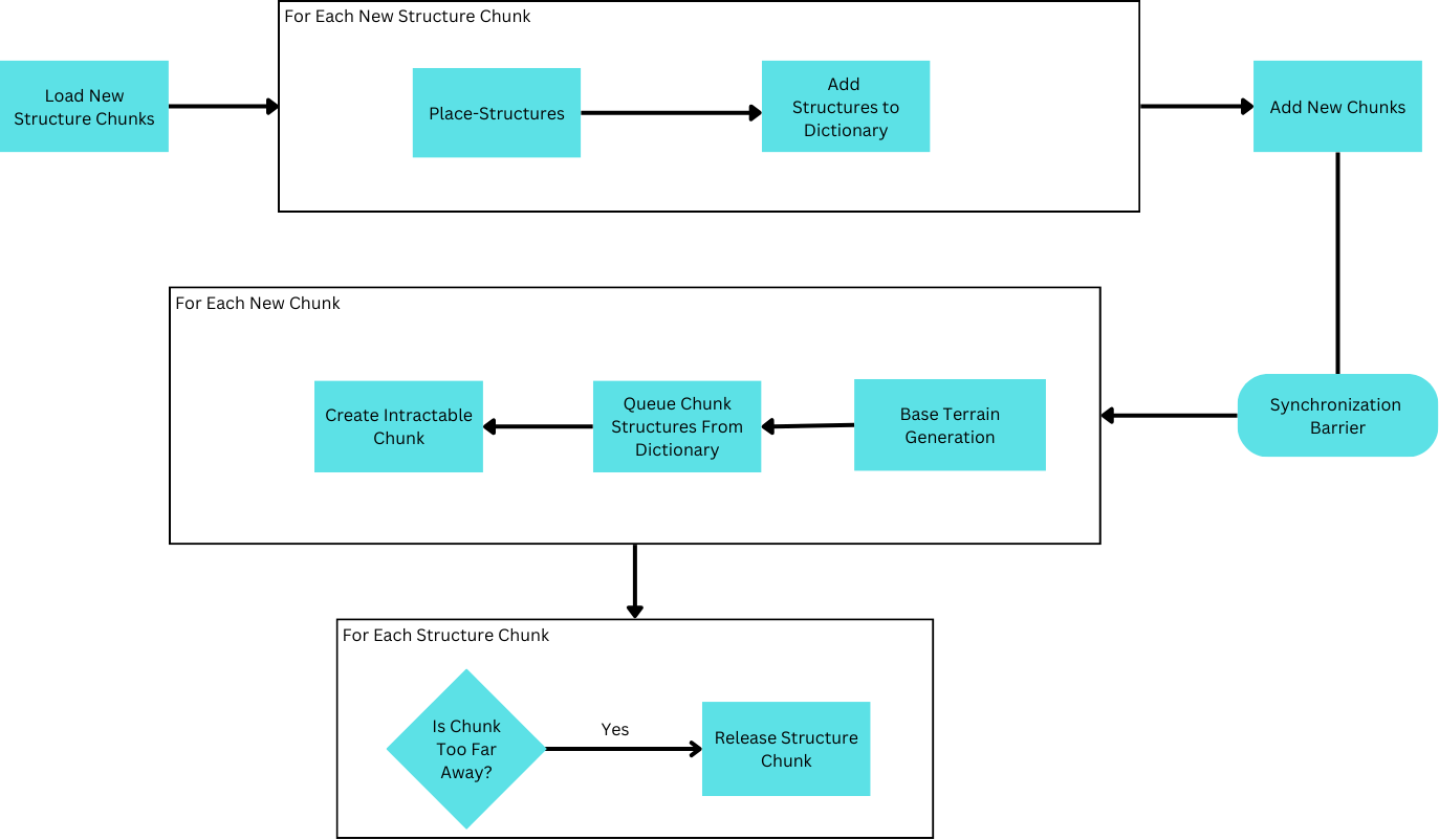
But this is all getting a bit overcomplicated. It would be far simpler & faster if it were possible to identify all the structures that could ever overlap with a chunk on a per-chunk basis, then releasing structures could be done in the same way as the rest of the chunk’s data.
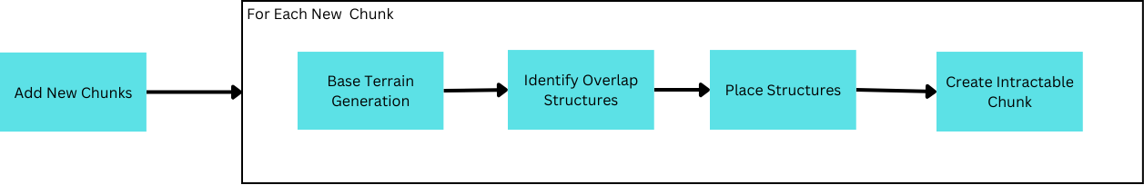
Hence, the process of identifying all structures overlapping the chunk being generated (structure planning), would enable structures to be compartmentalized in the same way the rest of generation is handled.
Specifications
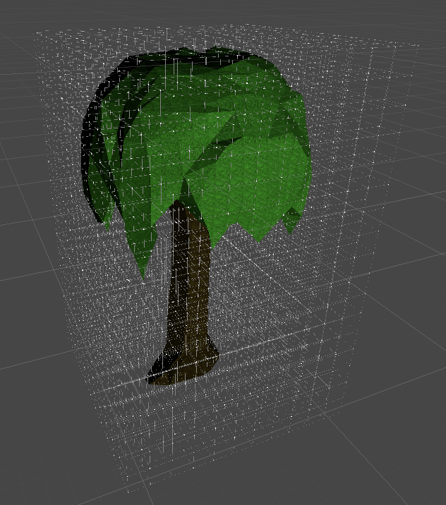
A structure is identified by an origin and structure-id. The origin refers to the position from which the placement of the structure’s data can be translated from. To plan a structure is equivalent to determining the type of structure to generate and the origin position from which to generate from. Each structure is also stored as a rectangular prism, where each data value contains information regarding the specific grid coordinate it resides at. Limiting representation to a rectangular-prism aids placement of structures in the future.
For simplicity, the origin of all structures discussed will be at the lowest coordinate position inside the structure. This ensures that given a structure whose origin is within a chunk, it may only overlap chunks of higher coordinate positions.
There is another requirement of determinism: that is, given the same seed there should invariably be identical terrain at a given location regardless of how the terrain is procesed up until the position. While this requirement is not always necessary, such deterministim is, more often than not, beneficial and will be adhered to.
Solution
Sampling
While some implementations may attempt to work through a list of structures attempting to place each one in a chunk, this will not be done due to scalability. Rather than requiring all chunks to evaluate the placement of every structure, it is far better to create the placement of multiple origins, and then determine the structure that may apply. Concurrently, structures may be deconstructed to an assortment of points representing the origins of the structures. With this, we can conduct a thought experiment.
Consider an infinite space filled with a relatively even distribution of structure sizes. Marking the origin of the structures, and removing the structures themselves, this space is now an infinite point cloud with a seemingly random distribution of points. However, as we are only concerned with structures that our current chunk is responsible for creating, most of these points are superflous so let’s isolate the points belonging to structures that overlap with the current chunk.
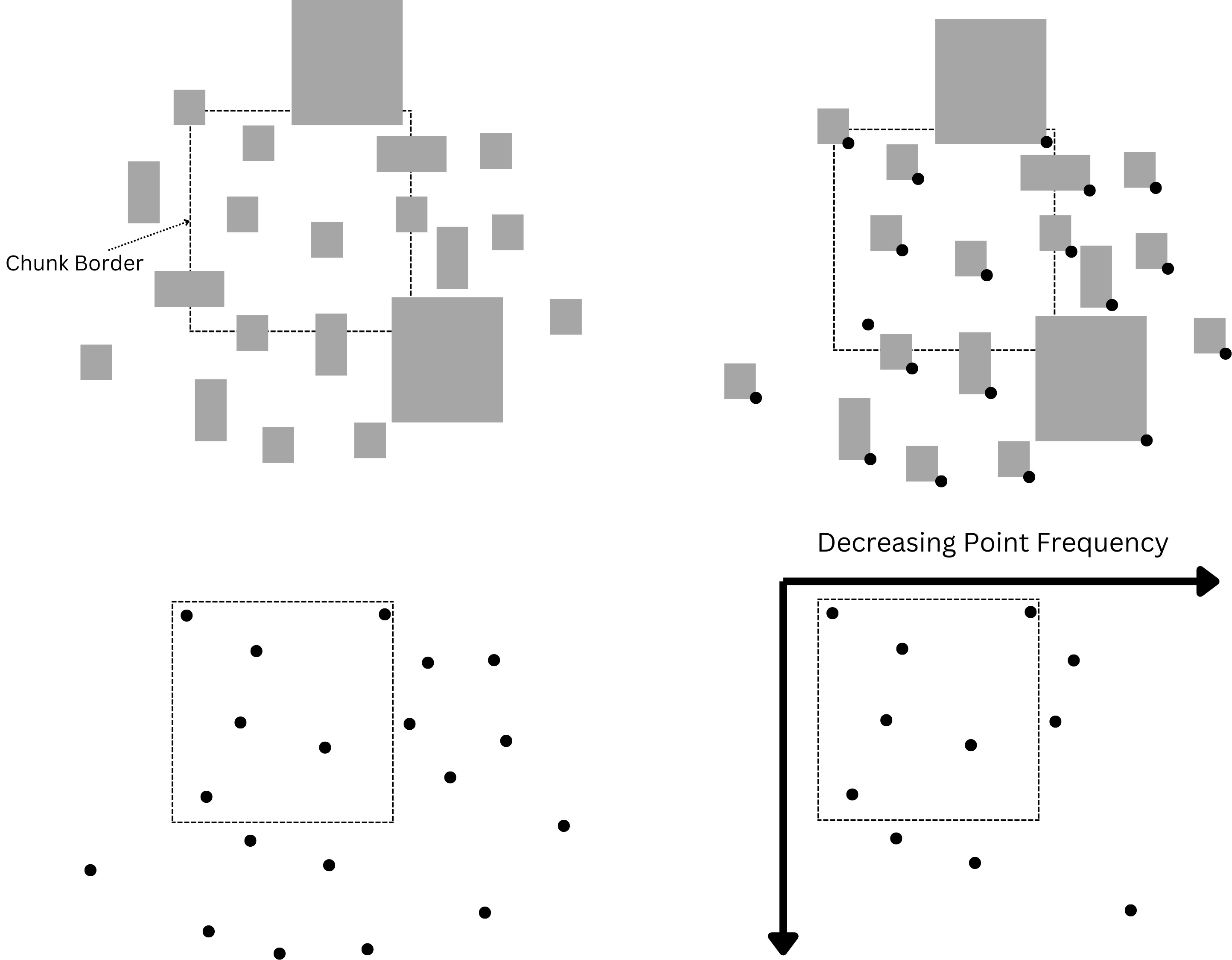
There’s a marvelous relation that comes to light; while points within the chunk maintain a relatively common density, as soon as we leave the chunk the point density begins decreasing. This makes sense as the further we move from the chunk, the larger a structure must be to overlap with the chunk.
Thus, considering this, the solution to Structure Planning can be said to hinge on the inverse of this property, whereby sampling a point cloud for increasingly fewer points as the distance to the chunk increases, we assign the size of the structure. It is crucial to realize the deterministic nature of this algorithm, however. In this case, it is vital that the point cloud in question is not an arbitrary point cloud taken based on factors unique to the chunk generating it in question. Instead, the algorithm may only function if the point cloud is indeed a singular point cloud such that two chunks may identify the exact same origin position given the structure overlaps them both. Accordingly, the question of interest is how to sample an infinite point cloud for points close to a given position?
To comprehend what makes a point cloud unique regardless of the sampling chunk, it is necessary to revisit what determinism means in computing systems. All random in computing systems is pseudo-random based on a set of factors, or a seed, which will unfailingly produce the same outcomes. To obtain the same outcome between two sampling chunks is consequently a matter of basing sampling on the same seed between chunks. Therein, an answer becomes apparent: to use the chunk’s position as the seed. However, this places a limitation as obtaining a chunk coordinate is necessary to sample identical points, point sampling may be destructed to units of no smaller than a chunk’s size to ensure neighboring chunks may reliably obtain identical chunk coordinates.
Having resolved positional sampling of a singular point cloud, there is the final hurdle of sampling fewer points further from the chunk. Fortunately, the answer is evident in the nature of the problem. For chunks further away, only few origins need to be sampled for the largest of structures while chunks nearer need both origins for large and small structures. By consequence, one may designate the first points sampled with a seed to indicate large structures with decreasing size as more points are sampled. Henceforth, a chunk may be able to sample only the largest structures without needing to parse all points.
Parallelization
Warning: The Following Section Describes Implementation Details Related To Accelerated Programming. The information here on foreward will be unrelated to Synchronized Implementations
In a synchronized implementation, this much may be enough to devise a solution. But when translating to a highly parallel system, there is an obvious inadequacy with the most direct solution. Such a solution would likely divide the work like so; as planning for a singular chunk requires distributed sampling across multiple chunk spaces where all origins bounded by a chunk space are dictated by a unique seed(the chunk position), this forms a mutually exclusive workspace for a thread allowing the work to be divded between chunk regions(25 in the diagram above). Actually, there are 3 dimensions these chunks are spread across meaning a maximum LoD of 3 with the same distribution pattern as above would spawn 125 sample blocks. This works out nicely for compute shaders which provide three dimensions of Thread Identification as this Id can be extrapolated to represent the offset Id of the sampling region from the current chunk.
Unfortunately, while this strategy divides-up the task, it does not do so evenly between all threads. Threads responsible for sampling regions close to the current chunk will find they have many more origins to generate than those far away. It doesn’t help that our current thread Id scheme groups sampling regions by physical proximity as this causes some worker groups to only contain sampling regions closer to the current chunk than other worker groups. Eventually, we’ll find that most threads will complete quickly and be waiting for a few threads given dense sampling regions.
To design a better work distribution strategy, we can begin by noticing a trend with our LoD. As LoD increases, the amount of origins in a sampling region of that LoD decreases; this gets to the point where an LoD of 3 will do only 1/10th the work of LoD 0 in the diagram above. Simultaneously, the amount of chunks that must sample origins belonging to an LoD of 0 is 8, while the amount of chunks that must sample origins belonging to an LoD of 3 is 125. In fact, we’ll find that generally the amount of origins sampled belonging to any LoD is roughly similar.
Amount of Origins in Each LoD(As Per Diagram extended for 3 Dimensions)
- LoD 0: (2*2*2) * 400 = 3200
- LoD 1: (3*3*3) * 300 = 8100
- LoD 2: (4*4*4) * 200 = 12800
- LoD 3: (5*5*5) * 100 = 12500
Of course, this depends on the falloff of origins with LoD, but commonly the falloff will be much higher than as depicted above. The ideal falloff is a function defined as y = 8 / (2 + x)^3 where y is the falloff multiplied to the base sample origin count(400 above), and x is the LoD level. All in all, if one could divide workload based on origin LoD, it could significantly improve the parallelism, and thus speed, of the system.
To do this, we can designate one DispatchID dimension to indicate origin LoD. Since aggregate threads on a compute shader can be envisioned as a cuboid, each LoD of our origin LoD dimension contains an even slice of the cuboid with an identical throughput(roughly at least ideally barring further abstractions).
Now that we’ve isolated an even resource division for each level of detail, the tricky part comes with dividing work between all threads in the layer. If we scale the remaining two dimensions to encode the chunk offset we run into a problem. If the remaining two dimensions are scaled to the maximum LoD’s sampling distance, then any other LoD will waste threads. Likewise, any dimensions smaller than that will have insufficient logical threads to sample the maximum LoD. In principle, having one logical thread sample every chunk will innevitably cause an uneven workload distribution. Rather, we need a distribution system that can remap multiple threads to one chunk depending on the LoD.
At our maximum LoD it’s meaningless to subdivide each regions task any further so each region can be designated its own logical thread. If the offset dimension of this maximum LoD is used as the other two dimensions, then we run into the aforementioned issue of wasted threads in lower LoDs. To resolve this, we can remap these wasted threads by performing a modular operation with the sample-region-size of the lower LoD.
It’s unfortunate that some regions will still have more threads than others, but to make this not the case would require LoD levels to be exponentially larger(i.e. all powers of 2), and anyways the difference in thread count cannot be greater than one. Having remapped multiple threads to identical regions presents a new problem: subdividing sampling within a region.
Firstly, to divide up a sample region we need to know how many threads are responsible for completing it. The number of threads mapped to the current thread’s sample-region can be determined using the formula below:
1 | uint remainder = ((maxRegionOffset % numRegions) < numRegionsMax % numRegions ? 1 : 0); |
Then if each thread is assumed equal responsibility of sampling origins, the total amount of origins the current thread is responsible for can be defined as such.
1 | uint numPoints = numPointsLoD[LoD] / ((float)regionOverlap) + random(seed); |
Finally, if each thread is responsible for only a fraction of the entire region’s origins, the problem now is generating unique origins on every thread that is still deterministic, hence identifiable by other chunks. This can be done like so.
1 | int overlapOffset = maxRegionOffset / numRegions; |
The overlap offset will provide each thread accessing a region a unique number seperating it from all other threads accessing the region. By factoring it into the seed, we can guarantee that the starting seed is(usually) unique from its siblings accessing the region. The LoD is also used to determine the seed, but to prevent mapping collisions(If LoD is 0 and overlapOffset is 1, it will be the same as LoD is 1 and overlapOffset is 0), it is first randomized. Finally the chunk coord needs to also be considered so it is first randomized for the same reason and then factored in.
For the proceeding seeds for each thread to be unique, the seed can be incremented by the chunkOverlap. This allows each thread to take responsibility for every ith origin such that no seed can be mapped to by two threads with unique overlap offsets.
Code Source
Optimized HLSL Parallel Implementation
1 |
|