
Overview
Procedural generation implies the production of new content based off of certain factors not unilaterally explicitly indicated by any individual. As computers are inherently deterministic systems, it follows that the sole way to produce undefined outcomes is to introduce randomness or noise into generation. This law is ubiquitous, notwithstanding of procedural terrain generation but found in all computer-related fields, notably machine-learning. As such, procedural terrain generation most commonly refers to the derivation of surface-terrain from a series of noise maps which dictate specific features of production.
Although this specific approach is undoubtedly effective for open largely unpredictable terrain, it lacks in reproducibility of certain strictly well-defined patterns which extends from the predictability of certain notable features observed in reality. Such features include trees, rocks, shrubbery, logs, vegetation, or given the specific application desired, roads, buildings, objects, spacecrafts, obelisks all fall under this umbrella.
While it is not impossible to layer noise maps to create specific shapes, and isolate these shapes to stepped noise regions, such an implementation is so unconventional and impractical that apart from extraordinarily unique cases should not even be considered. Another option is to isolate such patterns from procedural generation entirely in both in-game representation and storage, such as replicating a mesh procedurally after each chunk generation, and storing these meshes as individual elements appending the scalar fields used to construct the rest of the chunk. For confined games where further abstraction is unnecessary and unaffordable, this is often the chosen approach. Nonetheless, such an implementation implies a fundamental difference in these patterns in representation and handling even when such dilineation is intrinsicly superficial. In such cases a unified system that does not differentiate such patterns following generation is to be desired.
Background
Structure Placement is the third part in a series documenting a strategy of procedural generating fixed patterns (structures). Previously, the process of Planning & Pruning have identified a deterministic set of structures which overlaps the working chunk, and thusfar has been generalized to be independent of the rest of a chunk’s architechture(in the essence that it does not concern itself with the specifics of how the chunk is represented), as to be applicable in various implementations. This will, unfortunately, no longer be the case as Structure-Placement involves thouroughly with the chunk’s data representation in order to determine what to persist and override; information on the chunk’s data representation can be found here.
There is a major deviation in structure placement incumbent on how structure overlap is handled. Structure overlap refers to the case where two structures are placed in close proximity such that a volume exists intersecting both structures in which the output may become ambiguous. Often, two strategies exist to resolve this, one where structure-overlap is highly undesirable and active planning is taken to avoid it, and another where it is deemed acceptable and, instead, strategies to work-around overlap are devised.
In the first case, a further planning step is commonplace, where structure origins search nearby positions on a grid defined by the desired maximum size or seperation size of structures to find overlap. Structures that overlap are then pruned leaving a random distribution of non-overlapping structures. See Poison Disc Sampling.
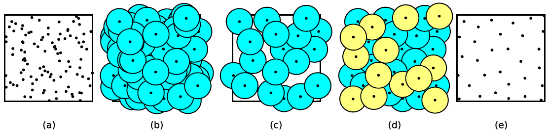
Maintaining a fixed distance of seperation through a further sampling step is often expensive, and moreover, enforces a strict minimum density of structures where it is impossible to place any more structures without reducing seperation distance. Rather, strategies to resolve overlap instead of avoiding it can often achieve much more natural results.
Specifications
Previously, Planning and Pruning underscored a need for a deterministic system such that two chunks can independently identify the same structure which intersects them both. Structure Placement, on the otherhand, works exclusively in the bounds of its own working-chunk and thus does not intrinsically need to be deterministic to achieve its goal(of placing the structure). Though it may not be necessary, being detreministic is often regarded as a benefit, partially because it allows easy recording and replication of procedural content because the conditions necessary to generate the same content can be exposed at a top-level. For this reason, structure placement, specifically overlap resolution will strive to be deterministic accordingly.
Solution
Before we begin, it’s beneficial to keep in mind where Structure-Placement is occuring in relation to the previous steps. While one may be tempted to attempt a prescripted method, there are several reasons to prefer placing after the ‘Base Terrain Information’ has been supplied. Firstly, structures may not completely occupy a chunk’s map data, unlike ‘Base Terrain Information’, and without manually obtaining clear memory(often inefficient when reusing memory), it would be impossible to determine if an entry is part of a structure or garbage data. Furthermore, responsibility for blending the structure and the base terrain, is best given to structure-placement which is not possible if ‘Base Terrain Generation’ occurs afterwards.
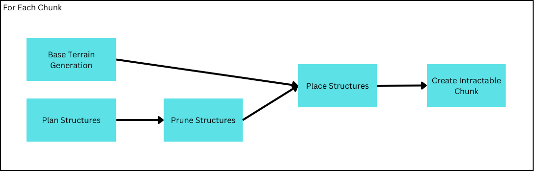
Like before, when exactly the planning and pruning step is not prescribed through this algorithm, though one may prefer to consolidate all Structure generation to occur after ‘Base Terrain Generation’.
Defining the Structure
Up until this point, structures have been construted as a cuboid because they are easy to describe (just three numbers are sufficient to express its bounds), and algorithms to map them onto a chunk are similarly straightforward. However, this limitation means all structures placed will have to be cuboids which will prove to be a challenge. For example, few trees are thought of to be perfect cuboids, so to fully encapsulate a tree in a cuboid, the tree must define its shape within the bounds of the cuboid while not adopting its shape itself. The point here is that the cuboid will encapsulate undesirable portions not part of the tree.
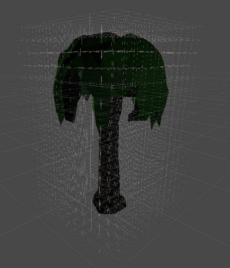
Note how most of the cuboid is not part of the tree
If the problem is that these portions which shouldn’t be part of the tree are placed alongside the rest of the tree, the solution must involve identifying these\ portions and choosing not to place them. One way of identification is that these portions aren’t solid(in our case the density is less than our defined IsoValue) while the rest of our ‘tree’ is. But this brings up two problems.
Though the not solid, or gas, portion of the cuboid may not be considered part of the tree, such a statement may not be invariably valid. In the case of this game, gaseous map-data is not discarded, but referenced by the Atmosphere Light-Scattering Algorithm such that the composition and density of the air is not trivial. But even in other cases, say an empty buried vault, often we want the gaseous contents to be preserved if only to maintain some empty space.
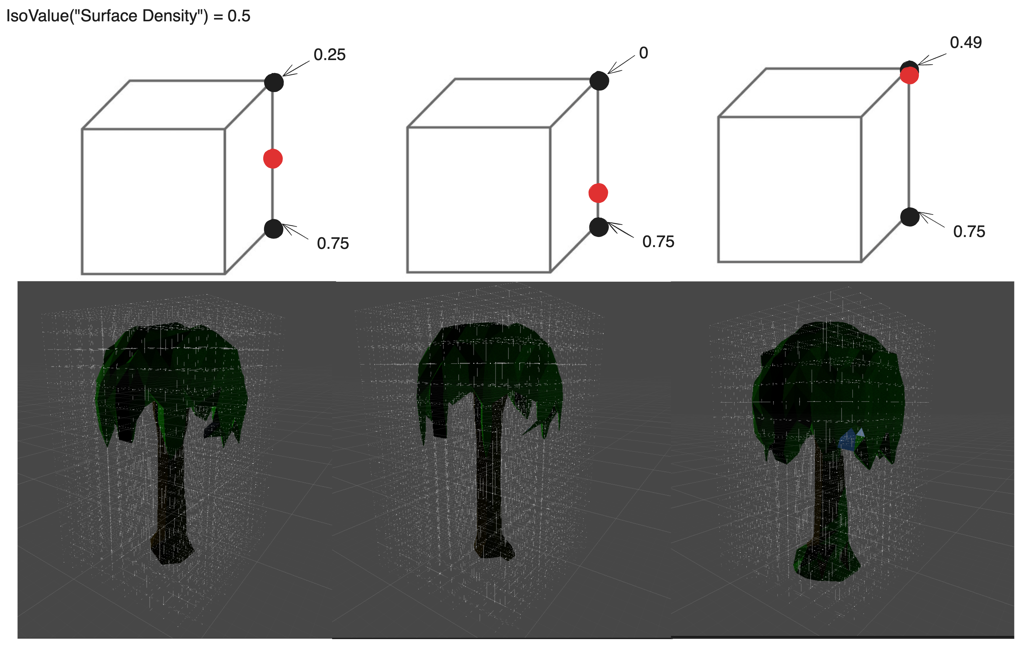
The second problem is specific to marching cubes: in particular that the surface is not only defined by the underground density, but additionally the immediately adjacent above-ground. To understand this, it’s first necessary to remember that marching-cubes attempts to identify triangles representing the surface of the ground, and triangles must have vertices defined on a marched cube’s edge. This means that if a marched cube has an edge with two parent corners, one underground and the other above ground, there must be a vertex between them, and conversely, vertexes only exist on edges of the same specification. To further smooth the ground, the position of this vertex can be shifted relative to the distance to the ground of each of its parents. If the underground parent is far below ground and its above-ground counterpart is only barely above ground, then the ground should be extremely close to the latter. Mathematically, it means.
VertexPosition = p1 + ((IsoLevel - p1Density) / (p2Density - p1Density)) * (p2 - p1)
OR VertexPosition = lerp(p1, p2, invLerp(p1Density, p2Density, IsoValue))
where p1 and p2 are parent positions, and IsoValue represents the density demarcated as the surface. Put together, this means, that to preserve the shape of a structure, it is not only necessary to maintain its underground informaition, but its immediately adjacent ‘gaseous’ information as well.
Parallezation and Racing-Issues
While parallelization of this process is not absolutely necessary, and other implementations may not encounter these issues, the challenges faced in parallelizing structure-placement are quite interesting. Moreover, my current implementation has thusfar been written for highly parallelized processing units(GPUs), and it makes sense to utilize these resources during placement. The reason for mentioning parallelization is that racing-conditions are a heavy consideration during placement, and the final solution reflects a thread-safe algorithm.
The unit that will be parallelized is each structure(i.e. a chunk generating 10 structures will register 10-threads to process each structure in a thread), and all structures in a chunk will attempt to process in parallel. Further subdivision of the task would overcomplicate the division of work and lead to an overall less readable and potentially slower algorithm. With this strategy, every thread will be responsible for copying all the data of its structure to the chunk’s shared map data.
Regrettably, this method complicates structure-placement further since overlap-resolution must not only account for resolving structure conflicts, but must do so in a thread-safe way(to be deterministic).
Underwater Structures
When placing structures, we should be clear on what information is being copied from a structure definition into our chunk. It is crucial to remember that both the chunk and structures are represented as map data, which in this case means 3 values: density, viscosity, and material. Let’s revisit the second problem with literally copying only underground entries by also copying adjacent above-ground entries. What we find is that structures originally underwater no longer make contact with the water.
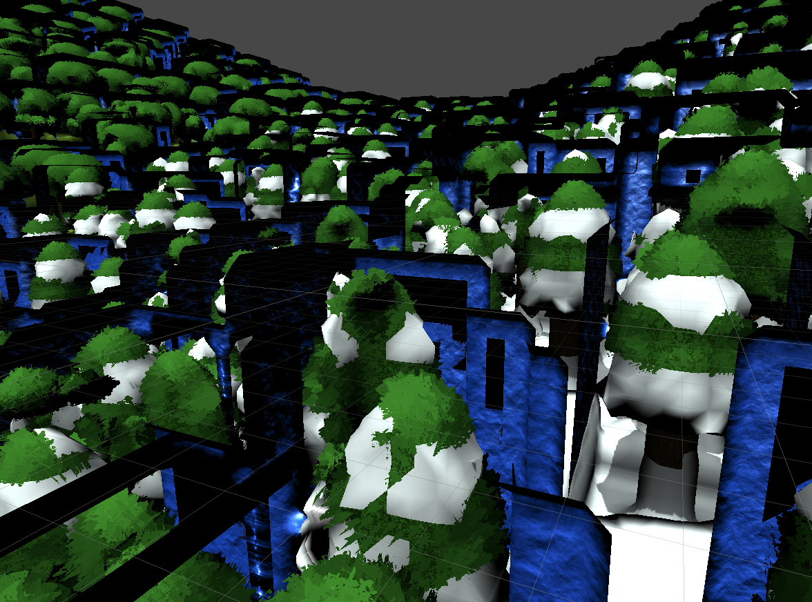
Notice trees are surrounded by water surface = they are not touching water
What’s happening is the viscosity of the structure is 1(i.e. 100% solid), so copying the viscosity of bordering above-ground entries means overriding what was once water on the chunk to become 100% solid and a density indicating it is above-ground, creating a border of air. This problem hinges on understanding how water generation works.
Considering only a solid world, the terrain shape can be fully described by the a scalar field of density. Given our definition of viscosity as “the percentage of density that is solid”, we would represent such a terrain by setting viscosity all to 1, as density 100% describes the solid terrain. Now for an above-ground point, suppose with a density of 0.3 & the boundary for the surface is 0.5, which we want to turn into a liquid, let’s swap the density and viscosity of that entry and breakdown what happens.
The solid density, which was originally : Density * Viscosity = 0.3 * 1 = 0.3
now becomes : Viscosity * Density = 1 * 0.3 = 0.3
The liquid density which was originally : Density * (1 - Viscosity) = 0.3 * (1 - 1) = 0
now becomes: Viscosity * (1 - Density) = 1 * (1 - 0.3) = 0.7
Thus, the solid density is preserved, while the remaining density is assumed to be liquid. This method has the exceptional benefit by preserving the solid ground’s shape by guaranteeing the same solid density.
Returning back to Structures, what this means is that when copying above-ground data into water, it is necessary for density to not be copied directly into the point’s density, but transcribed into the points viscosity instead–that way the structures shape is preserved(as density here is 1) while the point remains underwater. However, copying density to viscosity does not work for solid above-ground densities because the point’s original density complicates matters.
Blending
So far, I’ve discussed various problems encountered when trying to implement Structure-placement that I will attempt to resolve by gradually solving every problem to construct a single unified solution.
Originally, the concept of identifying the structure within a cuboid was dicussed as necessary to identify which entries to copy and which to ignore, but this becomes ambiguous with adjacent above-ground entries which also describe the structure’s shape. Rather than identifying what to include and not, a different conclusion can be reached realizing that what we want to remain is usually the maximum density between the structure and the base terrain. Structure’s generating into open air should replace the air while open air in the cuboid should fail to replace the (denser)ground. With this we can begin constructing an algorithm
Map.Density = max(Map.Density, Structure.Density);
But there is no way to forcefully generate open-air now, because it would just get replaced by the ground it was generating into. Here we can cheat max slightly. By using our highest bit as a force-marker, we can force max to take our structure’s density and use the rest of the bit to indicate density. Density & Viscosity are represented as uints here because they describe a finite range, 0->1.
Map.Density = max(Map.Density, Structure.Preserve ? Structure.Density | 0x80000000 : Structure.Density) & 0x7FFFFFFF;
Currently, if we try to do this for overlapping structures while processing parallel, the result will still be unpredictable as there is no way to know which max actually overwrites the data. Luckily, many language supporting threading also support atomic operations, which provides a thread-safe option to conduct an InterlockedMax, you can read more about atmoic operations here. Readjusting we get.
Map.Density = InterlockedMax(Map.Density, Structure.Preserve ? Structure.Density | 0x80000000 : Structure.Density) & 0x7FFFFFFF;
Thus far, we’ve only discussed density, but there are two other fields that need to be transcribed from the structure. To make materials thread-safe, we have to also perform an atomic max, but we can also force it to overwrite the base terrain.
uint force = Structure.Preserve ? 1 << 31 : 0;
Map.Density = InterlockedMax(Map.Density, Structure.Density | force) & 0x7FFFFFFF;
Map.Material = InterlockedMax(Map.Material, Structure.Material | force) & 0x7FFFFFFF;
If we try to tackle Viscosity in the same way as density and material, we get the same issue where the air will override water leaving an unnatural gap between the structure and the body of water it is generating into. Our solution was to swap density and viscosity, but that would introduce a lot of complications to determine when a structure is underwater(especially parallel).
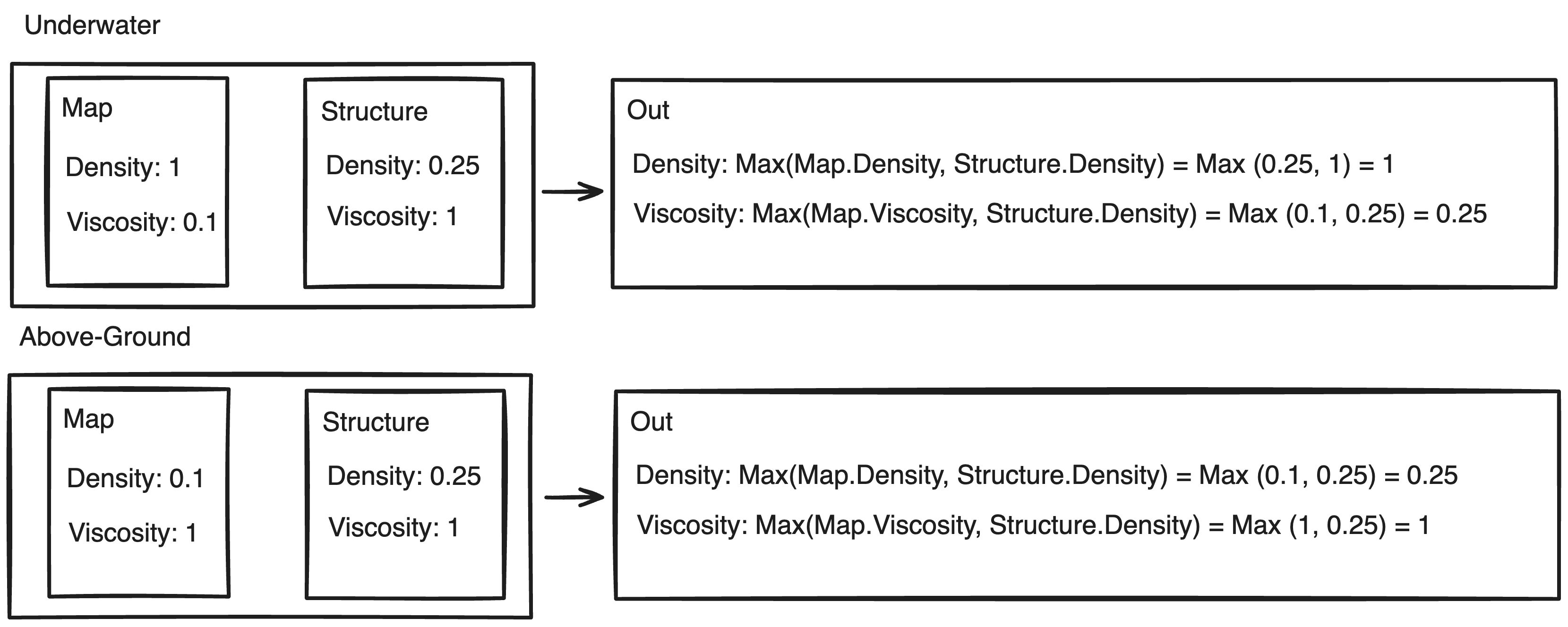
There’s a realization to be made here. For solid terrain, viscosity is invariably 1 or 100%; to make liquid terrain, the values for density and viscosity are swapped meaning density is 1. If density is 1 for liquids, then taking the maximum with the structure density always result in 1. Since our plan is to swap density and viscosity when generating underwater, we plan to assign the viscosity of our structure(which is always 1), but there is no need to do this because the maximum will always return 1. In the same way, if we are generating above ground, the base viscosity must already be 1, and thus taking the maximum with any value will be identical to manually assigning it to 1(our structure’s viscosity). Coincidentally, this means viscosity just needs to be the maximum of the base viscosity and the structure’s density, as this action will effecitvely swap structure’s density and viscosity if underwater, and only change density if on solid terrain.
Thus we reach our final placement strategy.
uint force = Structure.Preserve ? 1 << 31 : 0;
Map.Density = InterlockedMax(Map.Density, Structure.Density | force) & 0x7FFFFFFF;
Map.Material = InterlockedMax(Map.Material, Structure.Material | force) & 0x7FFFFFFF;
Map.Viscosity = InterlockedMax(Map.Viscosity, Structure.Preserve ? force | Structure.Viscosity : Structure.Density) & 0x7FFFFFFF;
Considerations
Until now I’ve only discussed 4 lines of code. To implement a functional algorithm, there’s a need to make-good on promises made in previous articles: particularly the claim that structures maintain one direction of generation regardless of their rotation. This means not only do rotated structures need to shift to maintain that they are generated from their bottom corners, but that since this bottom corner may be shifted, hence, no longer the defined origin from which this structure was originally defined all entries in the structure’s map data must first find their position in respect to the new corner.
Ultimately, all 90o rotations of a structure can be expressed as permutations of different axises. Given 3 axises there are 6 unique ways to permutate these axises, however these only account for half of the possible rotations. The other half are variations made by reversing certain axises, aka flipping. Put together, all 12 90o can be deconstructed to axis permutations & flipping.
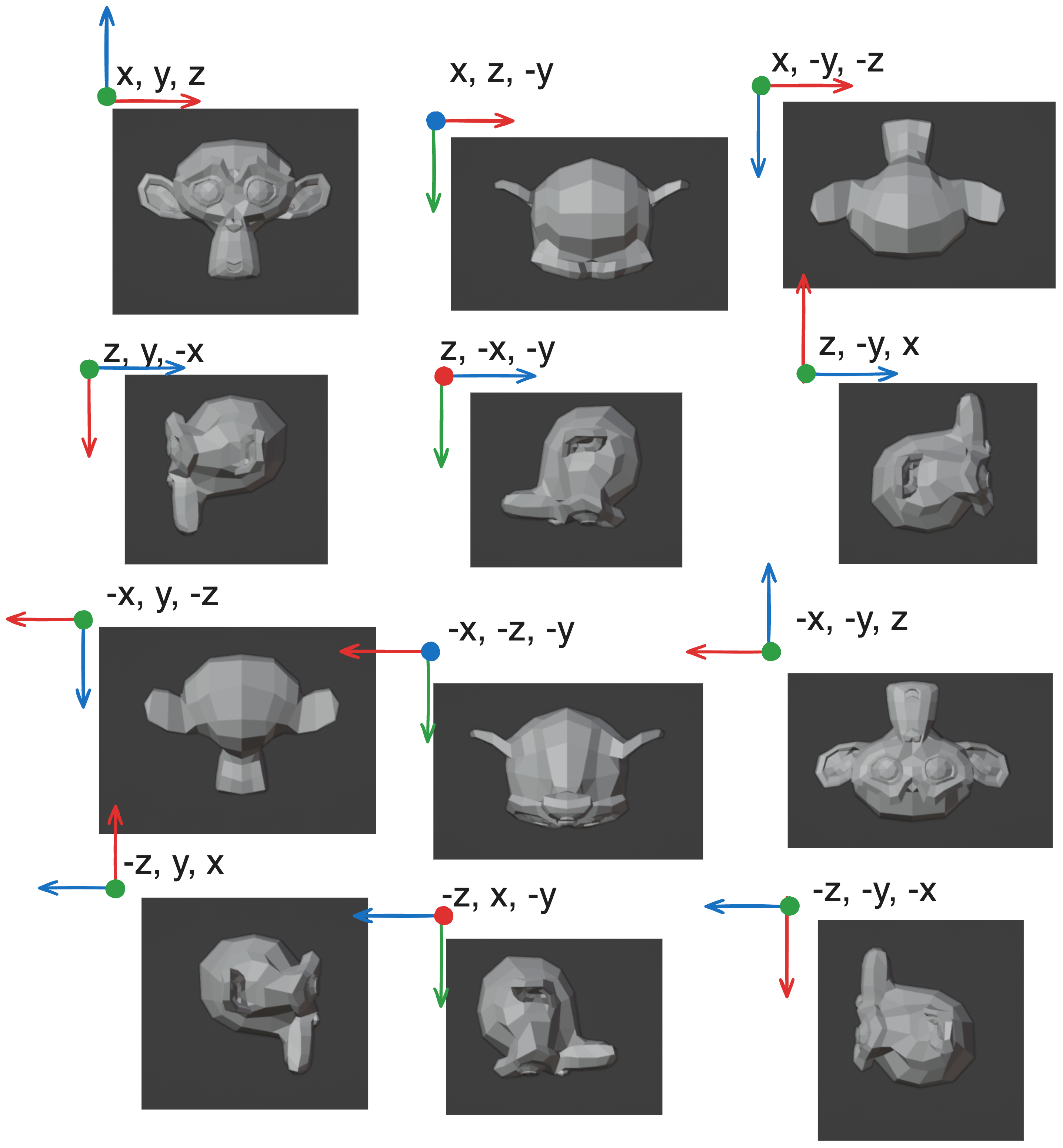
As Structure data is stored as a continuous array of information, one must hypothesize that it is possible to simulate such transformations by simply changing the way they are reading the information. Then, by writing only in a positive direction in the chunk from the origin, one is able to maintain one direction of generation while properly mapping rotations. Thus, to map data using these axis transformations is equivalent to finding the correct access pattern that transforms the data. Given that a structure is stored as a list such that the index is calculated
index = x * size.yz + y * size.z + z
If such an access pattern corresponds to an axis permutation of (x,y,z), it is plain to guess how to create other access patterns. Axis permutations simply equates to switching the major and minor array dimensions, and flipping translates to incrementing backwards along the dimension. For instance, an axis permutation of (-z, y, x) would mean
index = (size.z - z) * size.xy + y * size.x + x
Code Source
Optimized HLSL Parallel Implementation
1 |
|