
Overview
In the early era of digital gaming, there weren’t many splendid visual effects beyond what was functionally necessary. But as time went on, much larger portions of the public began to gain accessibility to increasingly powerful machines allowing developers to attempt to capture more and more intricate effects not previously thought feasible. As of today, many of these effects have amassed so much noteriety that their presence is almost expected of any high-end game. Notably, geometry shaders refer to a set of effects that have become commonplace in many new high-quality games.
A geometry shader(GeoShader), is commonly a name given to a shader stage that generates new geometry based on existing geometry from outside the render pipeline. As these new primitives are each generated from a base primitive, they usually inherit only information about their base primitive and thus are often used to elevate their base geometry rather than model a new shape. They are often used to enhance certain visual effects in a quick way and are traditionally used for complex visual features such as leaves, grass, hairs, smoothing, etc.
Background
It’s hard to imagine the potency of GeoShaders without some concrete examples. Having previously discussed the system and definition of geoshaders I will be using–it’s only fitting that some concrete applications of the system within the game be shown. Though the possibilities for unique geometry generation may be limitless, identifying a useful pattern may not be as simple. Further optimizing it to be applicable in a wide range of effects is even more challenging. Fortunately, several techniques are frequently used and have proven their utility in a wide range of applications. Understanding how to refit these ideas within our system may likewise offer insight into how they may be best used.
Specifications
Now that we’ve established a basis for procedurally generating geoshaded geometry, we need to identify a good set of geoshaders to support. One may be tempted to employ a dynamic amount of GeoShaders, perhaps one for each material, or allow each material the option to include its own geoshading logic; but this would be misguided.
Due to the design of our model, there exists a fixed-sized overhead for each additional geoshader one may attempt to support that will factor into every chunk regardless of whether or not it contains a material fitting the geoshader. Firstly, to even sort all the geometry in the described way, the total amount of possible geoshader types must be known in advance to allocate a guaranteed exclusive counter for each variant. Even with a fixed amount of geoshaders, one must still zero every counter establishing an unavoidable overhead, though it is negligible in almost every scenario.
The real bottleneck is in calculating each base geometry’s uniquely defined generation. As discussed previously, the GPU is uniquely optimized to handle multi-data instructions by preloading a tasks’ small set of instructions onto its processor’s cache before executing it for a large amount of data. The whole point of batching is to avoid this issue–but if there are too many batches the runtime quickly decays as the time complexity grows linearly with each new batch.
The problem is that the CPU is responsible for assigning tasks(and their associated instructions) to the GPU even if it is not aware of the specific contents of what is being generated. Although a chunk may not need to process a certain geo-shader if none of its mesh-primitives use it, because nowhere is the map information or mesh data readback to the CPU(which would be costly), the CPU must assume that all chunks are capable of applying it, hence loading its instructions even if it is immediately discarded.
Case in point, it is imperative that a small set of geoshaders be created that is capable of supporting a variety of purposes. Should a material require a special effect through geoshading it should look to reuse this set of geoshaders, possibly applying unique settings defined by the base geoshader it is using or how the created geometry is rendered.
Shell Texturing
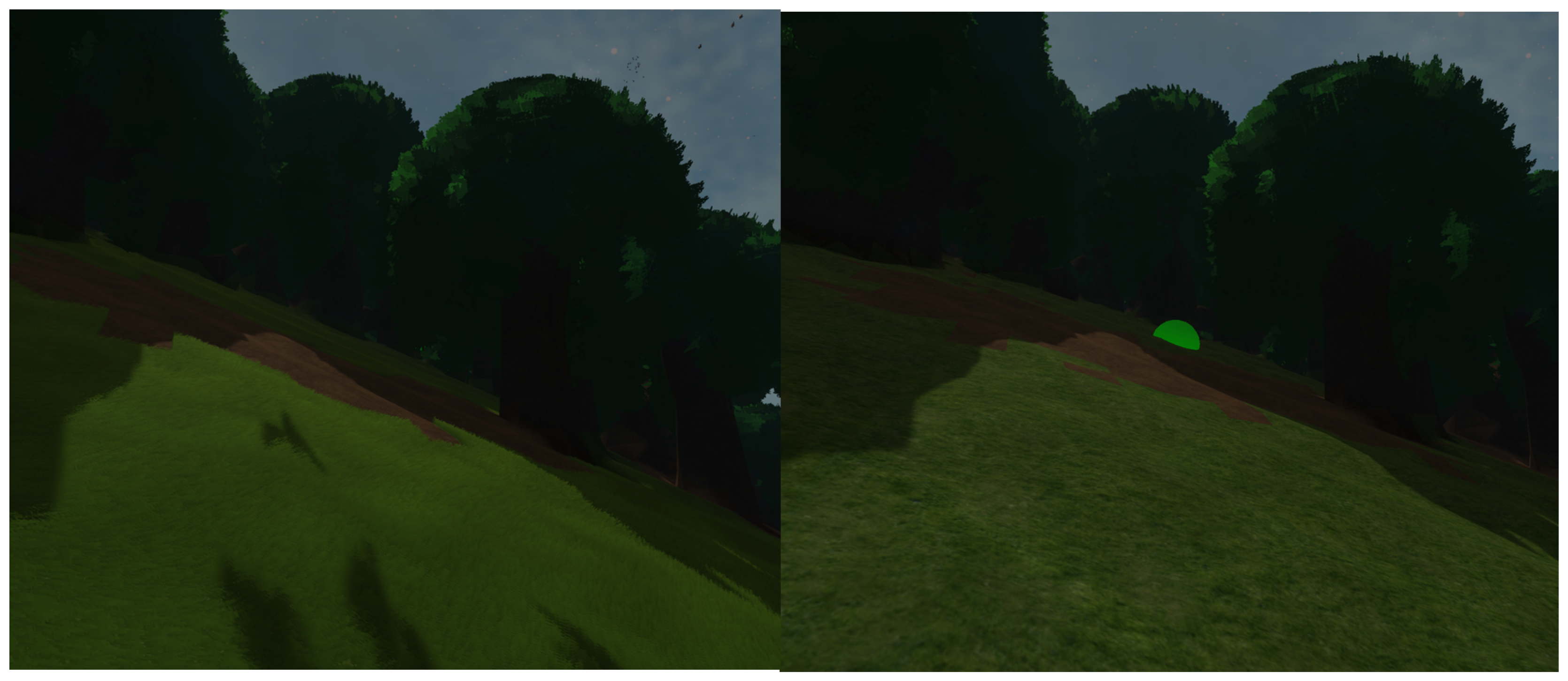
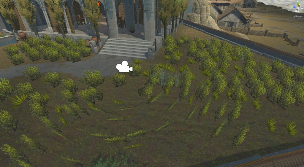
To start, one portion of the world that is glaringly lacking is the grass. By displaying only a simple texture, our grass emanates the same low-poly almost hard impression akin to an early nintendo game. While this aesthetic may be desirable for some, often times the hard/flat appearance may come off as uninviting; as in a player may feel much less comfortable sitting down on a hard plane than a soft flowing field. Concurrently, many modern open-world games have pivoted from this simple but cheap method in preference for a more immersive approach.
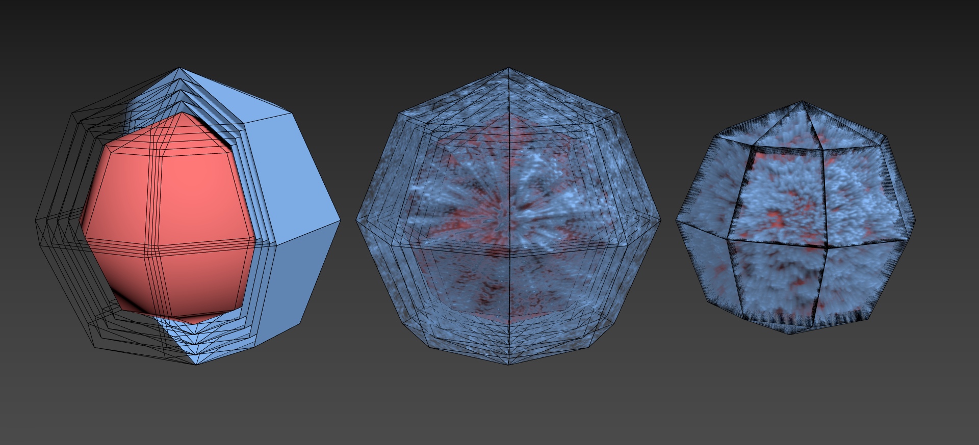
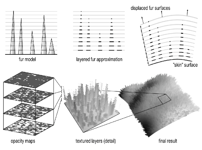
Among these approaches is one known as shell texturing, a technique also used for dense hair/fur shading. Contrary to more common techniques of creating a single quad/triangle for every blade of grass or using Quad Intersections, shell texturing involves stacking many primitives atop one another and cutting the desired shape out of the layered geometry. Or in other words, it’s similar to carving out a shape from a stack of pancakes. This idea isn’t unique to rendering grass or fur. Notably, due to the unique quality of the generated geometry becoming less visible when viewed in parallel to the stacked planes, this form of layered mesh is often used to communicate the intangibility of certain objects in games, such as a holographic projection, or employed in some simplified models for orthographic parallax.
Implementation
Generating the geometry is relatively simple. An outer “shell” surrounding the base geometry can be generated by duplicating each triangle and extruding each vertex about the normal direction at its base location. Conceptually, each layer is created by moving each base vertex a fixed distance in the direction away from the surface relative to the vertex, and each successive layer need only be moved an increased distance to form a multi-layered shell.
However, a prerequisite for this method is that each vertex needs to store its own normal (direction away from the ground). Generally, most pipelines have this information as the rasterizer, the process responsible for determining which pixels a primitive draws, must determine the pixel’s normal from the vertex information–but determining each vertices normal is quite complicated.
Physically, the normal for any plane can be determined by the unit cross product of any two unique vectors on the plane, or conveniently the edges of the primitive. The exact order the edges should be processed in the cross product is determined by the Winding Order of the graphics system being used. This determines the normal of the specific plane demarcated by 3 vertices, but as each vertex may simultaneously define other planes we run into an issue.
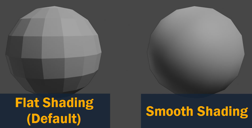
One option is to accept all normals of planes bordering a vertex by duplicating each vertex for every plane it defines. This results esult in a type of rendering known as flat-shading, whereby because the blended normal changes abruptly across the edges of a primitive, the boundaries of each primitive are sharp. The alternative is a method known as smooth-shading whereby a vertex’s normal is determined by blending the normals of all primitives(triangles) it defines by scaling the influence of each normal by the inverse distance from the vertex to the centroid of the triangle. This results in a smoother look whereby the normals change continuously across a surface.
Luckily, marching cubes offers us a way to determine smooth normals off the base map information generating it. This is because mathematically, our normal may be described as the negative gradient of the density function at the vertex’s position. This allows us to determine each vertice’s normal without needing to work with the outputted triangles.
With the generated shell, the only remaining step is to carve our shape from the layers. The benefit of shell texturing is rather than carving a shape through direct mesh manipulation, we can achieve the same result by selectively disabling(clipping) certain pixels from being drawn within each layer. By not writing to the depth buffer as well, this allows the layer behind it to render through the holes effectively achieving the same effect as direct mesh manipulation. This reduces the load on the Input Assembler and general memory consumption at the cost of slightly more work for the fragment shader step (see here for more info), but as we don’t expect too many layers to be rendered here, this tradeoff is very much advantageous.
Each layer of the shell represents a topological slice of the object, or a level curve of the surface at a certain height. While for a more complicated object, sampling this curve for varying heights may prove difficult; grass often follows a very simple pattern. That is, as the height of the grass increases, the level curve relative to each layer should shrink. If one imagines a 3D surface defined by an arbitrary 2D heightmap(e.g. a noise texture), this can be said to recreate the surface through a set of planes intersected at varying heights.
To describe more complicated shapes, one would innevitably require a 3D texture as it is impossible to fully describe a 3D shape with only 2 dimensions of information, however some simple shapes may still be replicable through clever usage of the multiple color channels or bitmasking in a 2D texture.
Remarks
There are some downsides to this technique. First and foremost, because each primitive doesn’t actually represent the surface of each blade of grass, if the effect is viewed parallel to its layer plane orientation, the grass can vanish; a problem further exasperated without backface rendering. Secondly, as the amount of layers strongly influences the quality of its apperance, for situations with low amounts of grass per base primitive, shell-texturing can be more inefficient than other techniques generating geometry per blade of grass.
On the other hand, there is an undeniable advantage to shell-texturing. Since the shape of the geometry is carved through selectively clipping pixels during the fragment phase of the render pass which is recalculated every frame, unlike other geometry shell-textured shapes are much more dynamic. This is a critical factor in enhancing the quality of our grass as the grass’s 3D shape can morph dynamically to reflect wind blowing through it beyond what is possible with fixed per-blade geometry.
Quad Intersections
By comparison, a much more simpler solution for many effects is placing an image billboard of the subject being recreated. An image billboard(a plane displaying the image) places very little strain on the pipeline as the content of the image compensates for the density of the geometry. Moreover, images are an easily readable and mutable format offering high control over what is displayed. It is no wonder that image billboards are seen everywhere in 3D retro games.
But as the billboard is a plane in 3D space, it is possible that the viewer is misaligned with the billboard causing the illusion to be broken. As billboards in these games were used sparringly for intangible background assets or character models, a common solution is to rotate the billboard based on the camera’s movement to always face the camera.
Regrettably, this is not a very scalable solution. Generally geometry isn’t built to be dynamic and forcing constant updates may be slow due to needing a seperate pass which requires write-access to shared memory in order to readjust the geometry every frame. Furthermore, camera-facing billboards are often unsightly once the player approaches them and can notice their rotation. Instead a different solution involves placing multiple billboards to account for viewer misalignment. Or in other words, using multiple billboards facing different directions to imitate a 3D object.
Implementation
Evidently, using static billboards to always display an image perpendicularly to the viewer would require an unreasonable amount of billboards, so a balance is needed. Usually, the amount of billboards used depends on many factors such as the direction the viewer is expected to look at it, the orientation of the image, or how the billboard are placed relative to one another.
One method I will refer to as outer intersection is formed when the billboards never all intersect at a single point but create an enclosed shape surrounded by billboards. In this case, it is possible for a position to be inside the image in the sense that every direction away from the point intersects a billboard. Contrastingly, the other method I will refer to as inner intersection involves all billboards intersecting at a single point such that no enclosed shape is formed by the planes. By the same definition, it is impossible to be inside the image with this form of intersection.
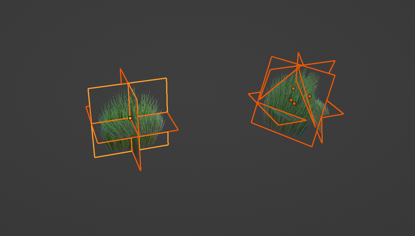
Beyond this, there is an uncountable amount of ways to arrange billboards depending on the needs of the situation, and the choice between either is highly dependent on developer preference and its application. But generally inner intersections are very simple to generate algorithmically. Specifically, 3 inner intersection quads(a plane) oriented along perpendicular planes as shown in the figure above is our preferred design for both simplicity and versatility.
Given that we have an image in mind of this placement pattern, a very simple tactic to recreate it in a geoshader is to literately store a base template of the geometry and translate it onto the location of the geometry that it would be placed upon. Each quad intersection maintains the same orientation thus resulting in a very sharp jagged look. This may be desirable in certain cases, but in Arterra, it would be better if our template rotated to follow the contour of the terrain everytime we duplicate it.
One way is to define the desired normal of the terrain in which the template does not need to be rotated at all. Then based on the normal of our base geometry, calculate the angle of rotation between the two vectors as well as the axis of rotation. This can be used to construct a transformation matrix which then may be applied to all vertices to rotate them to align with the terrain’s normal.
Alternatively, rather than duplicating a template, we can use the normal to create our quads programmatically. To create the vertices of a 3 quad intersect, all we need to do is find 3 orthogonal vectors. This is because 3 quads are perpendicular to one another if each has a normal vector that is perpendicular to the normals of all other quads. By finding 3 orthogonal vectors, A B and C, one can create 3 quads through using vectors AB as the tangent vectors creating the plane with normal C, BC as the tangent vectors creating the plane with normal A, and AC as the tangent vectors creating the plane with normal B. By using our terrain’s normal as one of these vectors, we can effectively rotate how the quad intersect is generated to follow the orientation of the base geometry.
With one vector as our normal, an orthogonal vector can be obtained by taking the cross product of the normal with any non-parallel vector. Obtaining a non-parallel vector from an arbitrary vector is suprisingly difficult without branching logic. For example, one way is to rotate it about some fixed axis; for example, a vector with components (C1, C2, C3) rotated 90 degrees about the z-axis will have new components (-C2, C1, C3). This will produce a unique vector for any vector that is not parallel to the z-axis; but if it is parallel the technique fails. Ultimately, the simplest complete solution may be just to maintain two arbitrary vectors to cross with in case the normal is parallel to one. With two orthogonal vectors, the final perpendicular vector can be obtained through a final cross product which is guaranteed to be perpendicular to either vector. Finally, any scaling of the quads can be done through controlling how far along each tangent axis a vertex is translated from the origin to form a corner of the quad.
Remarks
Although billboards are usually quads to reflect image formats, triangles are the preferred method of 3D geometrical representation as each triangle uniquely defines a plane. Conveniently, quads can be split into two triangles by splitting the rectangle on its diagonal. Though many pipelines already deconstruct quads by themselves, maintaining consistency of representation may be beneficial going forward.
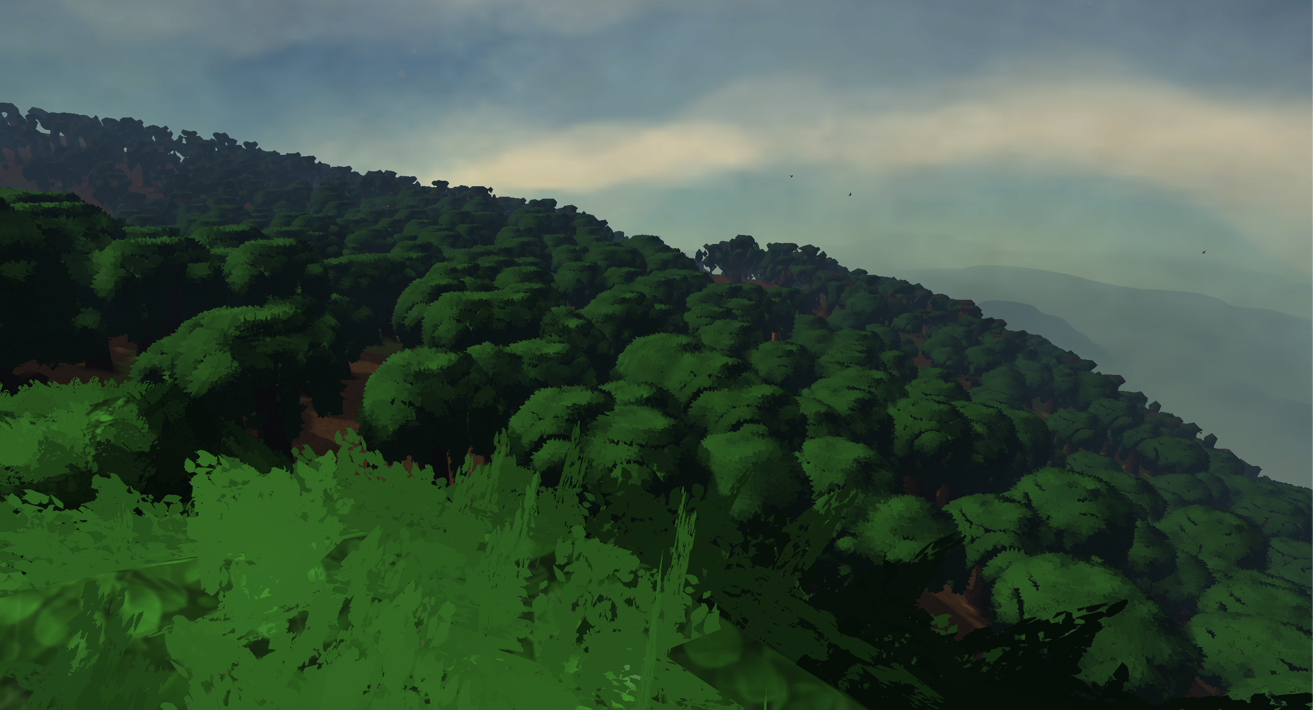
Quad intersections are mainly used to display foliage(specifically leaves) in Arterra. Following an example using camera-facing billboards (see here), they break up the edges of trees making them appear fuzzier and softer. Wind can be replicated through stretching how the texture is sampled when drawing to each billboard.
Tesselation
In traditional terminology, tesselation refers to a step outside of geoshading used to subdivide the base geometry in order to add finer details, such as decimating or adding texture to the surface. Obviously as we’re not using traditional terminology, tesselation in our custom geoshader system will refer to a custom geoshader which tesselates(subdivides) the base geometry and can offset each vertex(add detail) all in one step without replacing the base geometry.
Moreover, tesselation is often a difficult process hidden from developes by many graphics engines. By investigating how it is implemented(more correctly reverse engineer its functionality based on its apperance), can be a vital resource for those searching for a more thorough understanding.
Implmentation
Triangle subdivision is a vast topic that is a subset of simplex(see here) subdivision; numberphile has a good video on the topic. To help us decide, there are some constraints and criteria we need to impose on the algorithm. Foremost, no vertex should lie on the edge of an independently adjacent triangle. For example, the subdivision strategy shown below violates this principle
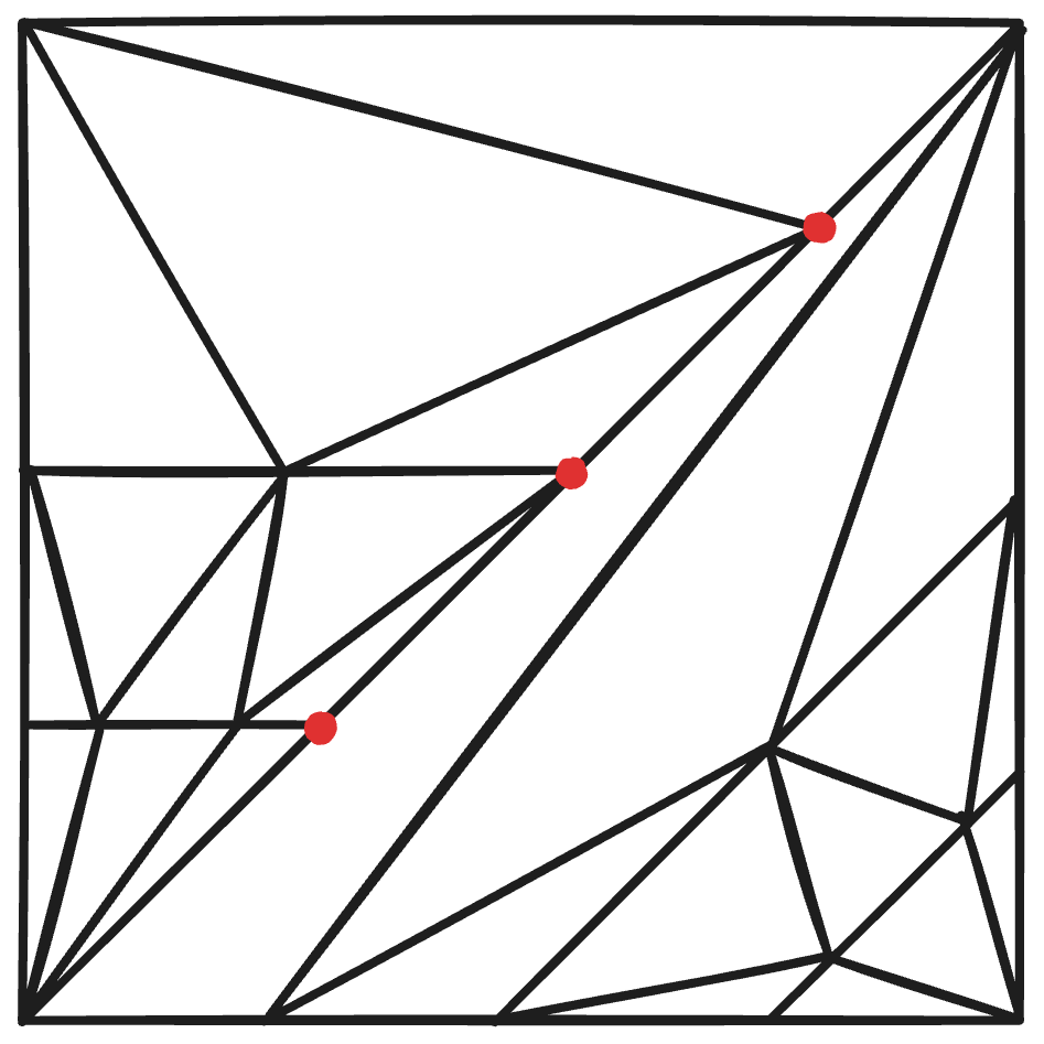
In effect, we want each edge of our base geometry to be subdivided identically by its neighbors. If such is not the case, what can happen is that offseting a bordering vertex could a gap to form as the duplicate edges may seperate. Other factors including prioritizing similarly sized triangles, reducing offensively acute/obtuse triangles are likewise also important.
Traditional geoshaders recieve two types of parameters in tesselating primitives–outer tesselation level and inner tesselation level. As is described in this OpenGL article, the outer tesselation level refers to how many subdivisions are made on each respective edge of the primitive and the inner tesselation level indicates how many concentric rings are used to subdivide the primitive internally. Because we require each edge to replicate the same amount of subdivisions, we can ignore the outer tesselation and focus solely on recreating the functionality of inner tesselation. The article provides the following diagrams.
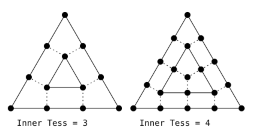
The inner tesselation level appears to correspond to how often the edges of the outermost triangle are subdivided: the amount of lines segments comprising each outermost edge. What’s more, each successive concentric rigns is defined by edges each with two less vertices/line segments than the ring before. This continues until at the base case a single triangle or a single vertex remains. The actual tesselated triangles connect between two consecutive rings filling the space with an even distribution of mostly similarly sized right triangles.
To start, let’s focus on creating these concentric triangles. The centroid of a triangle can be found by averaging the positions of each of its 3 vertices; if we draw a line from each vertex to the centroid we can place verticies along evenly distributed segments on this line by interpolating between the two positions. position = baseVertex * t + centroid * (1 - t) where the progress t can be found through t = ringIndex / totalRings. Connecting each vertex to the two others at the same ringIndex on the opposing line segments creates a set of concentric triangles.
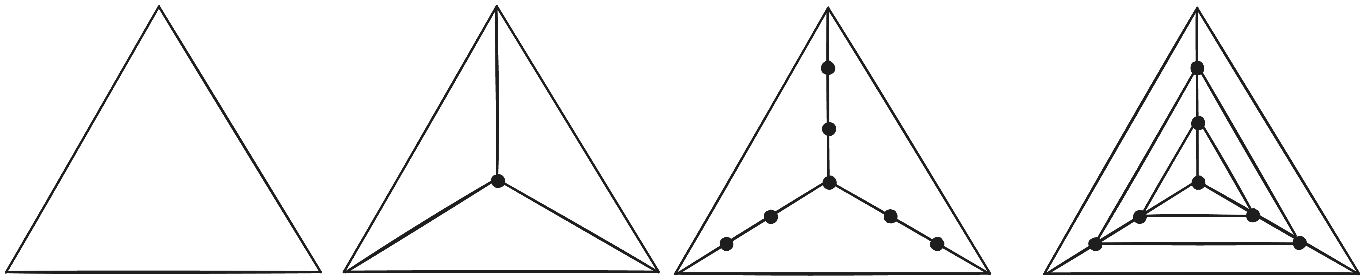
Then, each triangle edge should be subdivided to create the vertices forming the base of our tesselated triangles. Because each concentric ring uses has 2 fewer vertices than the ring around it, we can work out the amount of times to subdivide each ring by the number of rings within it, or conversely, determine the number of rings by the amount of times we subdivide the outermost ring. If the inner tesselation factor describes how many times the outermost ring is divided, the formula for the number of rings(including the center vertex) is ⌊Inner-Tesselation/2⌋ + 1. To subdivide each edge of a ring, one can similarly interpolate between the two endpoints of the edge by the progress(t)t = VertexIndex / NumberOfRingSubdivisions to evenly distribute a set of vertices.
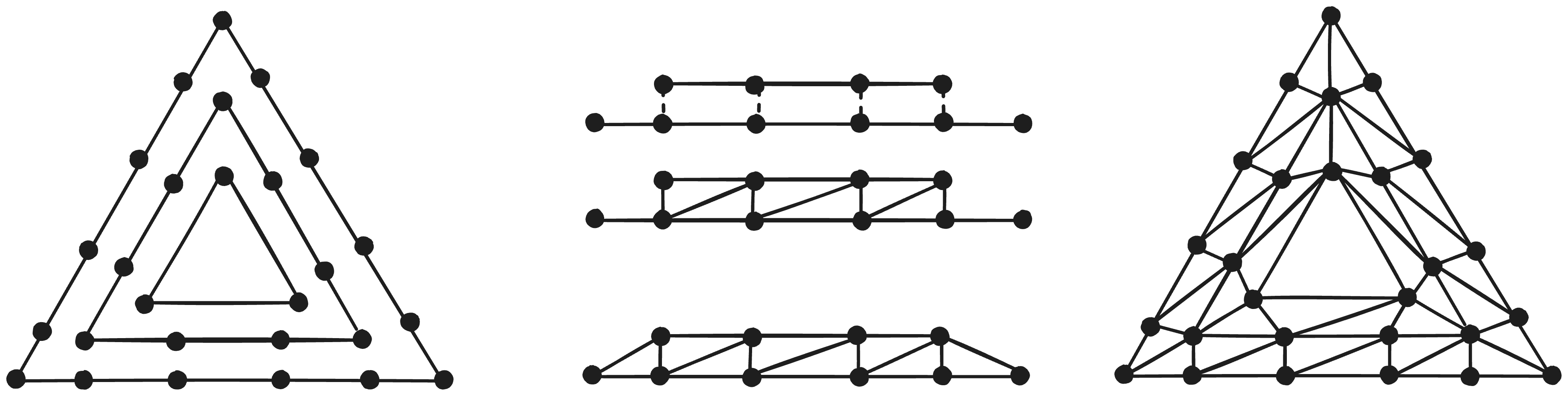
Now to connect the triangles, one can notice how between the edges of two consecutive rings, if one ignores the outermost 2 vertices on the larger edge, one can obtain a bijective mapping between either edge’s vertices allowing them to be paired one-to-one. Each pair of vertices form a rectangle with the next successive pair, allowing us to subdivide the region into a chain of rectangles. This is beneficial because rectangles have a very straightforward triangulation pattern(splitting it down a diagonal), that is replicable throughout the length of the ring.
Finally, the last two vertices of the outer ring can be triangulated by connecting with its next adjacent vertex and the final vertex of the smaller ring. Notably these two end triangles are static components of every pair of rings and can be added statically regardless of the size of the edges. Repeating this winding pattern 3 times for each pair of edges allows us to fill the gap between two rings which then can be repeated for every concentric pair of rings.
Remarks
Often times, due to limited interest in geoshading and tesselation, they are sometimes criticized as being unnecessarily slow/unoptimal from lack of research. For instance, Tesselation generates a large amount of duplicate vertices, vertices shared by multiple triangles, which could ideally be reduced through a seperate index/triangulation buffer specifying indices within a vertex buffer storing the data of all vertices void of any duplicates. Though this approach may be simple in a single-threaded environment, coordinating duplicate removal across multiple threads whereby each thread is responsible for a base primitive which can share vertices across edges is rather difficult. Nevertheless, due to the high reusability of tesselated vertices, pursuing this form of optimization could still be worthwhile.
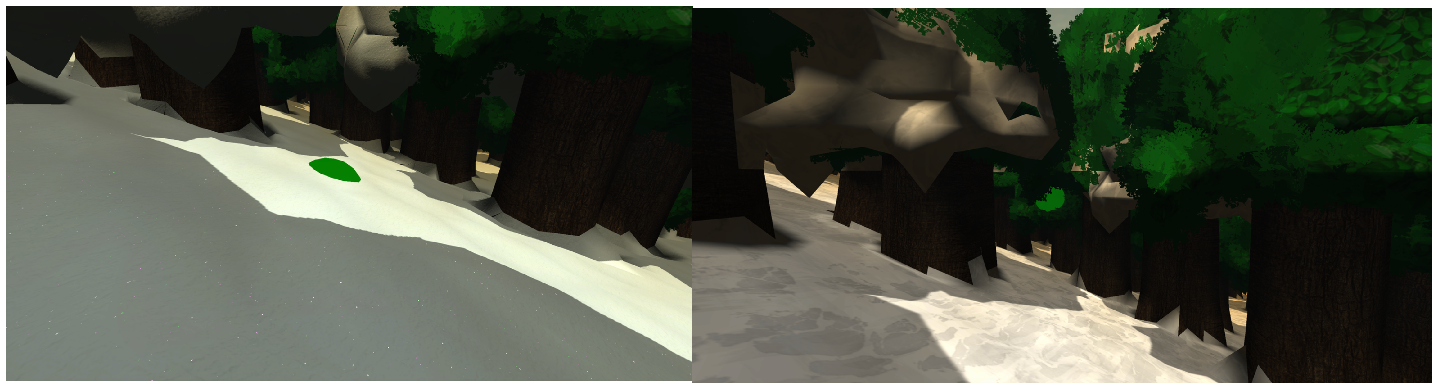
Tesselation is used in Arterra to create a detailed snow surface above the base terrain that is intangible, thus allowing collider objects to appear to sink into it. The surface of the snow also appears more detailed and varied than the maximum resolution permitted through the base geometry, enhancing its immersivity.
Code Source
Optimized HLSL Shell Generator
1 | // Each #kernel tells which function to compile; you can have many kernels |
Optimized HLSL Quad-Intersect Generator
1 | // Each #kernel tells which function to compile; you can have many kernels |
Optimized HLSL Tesselator
1 | // Each #kernel tells which function to compile; you can have many kernels |